Every 3D-printed object you have held began as a shape, sliced into layers by software.
These did not. The machine's own instructions are written directly, every coordinate and
every millimetre of extrusion, and the object is whatever that motion leaves behind.
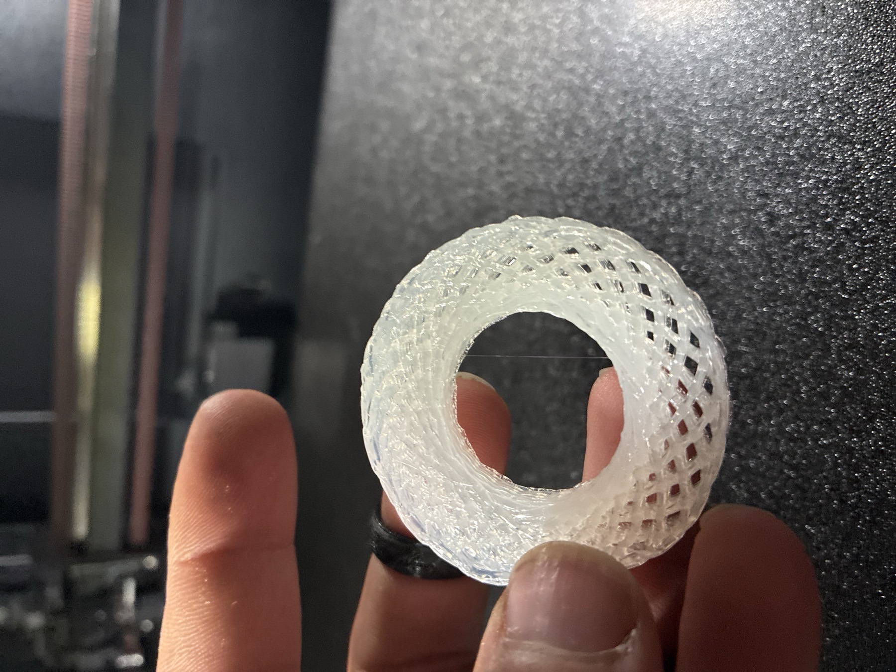
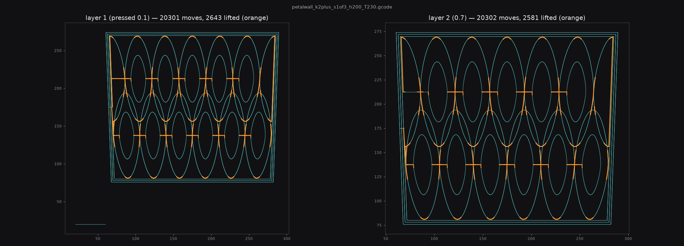
NUCLEON: 6 ellipses · 74 crossings per layer, 38 fused and 36 stepped over
No CAD
Nothing is modelled. The geometry is a parametric curve evaluated straight into machine
coordinates.
No slicer
Nothing is sliced. A slicer's job is to make a closed shell succeed, which forbids exactly
what makes these objects interesting.
No equivalent
Strands that cross without merging, density that varies continuously, structure that is a
consequence of motion. There is no setting for any of it.
The path is the product
A slicer exists to turn a solid into a shell and fill it in. It is very good at that, and it
is built to prevent the things happening here: it will not let a strand hang in the air across
a void, or cross another without merging into it, or thin out to a filament and thicken again
within a single move.
Writing the motion directly removes the intermediary. A curve is chosen for what it does
physically. How many times it crosses itself, how long the unsupported spans
between those crossings are, whether the head can hold speed through the turns. Then it is
emitted as coordinates. The object that results was never drawn.
The obvious objection is that slicers save material too. It deserves arithmetic, not a
shrug, so it has its own page: could a
normal slicer have made this bucket? weighs a 340 mm bucket, mid-print when
that page was first written and since completed and accepted, against every slicer
feature that comes close, all of it measured from the emitted file.
Everything here is measured
None of these numbers were chosen because they seemed reasonable. Each was measured on the
machine, and most were learned by breaking something first. Several have been measured
twice. A flow ceiling taken while a nozzle was quietly clogging was discarded
outright rather than trusted, because a number gathered under a fault is not an
approximation, it is fiction.
The last row is the one that changed how the work is planned. The machine with the
wider nozzle passes less plastic: 1.56× the orifice area, 0.80× the
flow. So the hole is not the constraint at all. The heater is, and the two machines have
different ones. A bigger nozzle buys a wider bead, never a faster print, which is the
opposite of the reason most people fit one.
This row was published wrong for an hour, claiming the two ceilings were equal. They are not.
The error came from treating the top of a test range as a measured limit: a ramp that ran to
60 and printed cleanly proves at least 60, and nothing more. The number here is now
the flow at which the extruder audibly skips, on both machines, found by widening the range
until each one failed.
Quantity
Value
How it is known
Landed bead width
1.53 mm
Derived, not calipered: a 3-layer probe measured 4.72 mm tall on 2026-07-25 and the width follows from it. That probe ran a 2.0 x 1.2 mm command, a bead retired the same day. See the note under this table
Deposit per layer
1.573 mm
Calipered on that same probe against its 1.2 mm commanded height. The excess went into height rather than width, because the nozzle never squashed it
Bead commanded now
1.2 x 0.6 mm
BEAD_W and BEAD_H in machine.py: 1.5x the nozzle wide, 0.75x tall, the most a 0.8 mm orifice will stack. This is the bead in the fragment below
Melt temperature
210 °C
The material's rating. Flow yields to it, never the reverse
Junctions per layer
74
Measured in the file. The formula 2N(N−1) predicts 60 and the generator prints it as a prediction; the emitted count is 23% higher
Symmetry penalty
2.0×
A regular grid halves your junctions; jitter recovers them
Planner ceiling
~300 moves/s
Above it the buffer drains and the head stalls
Nozzle vs flow
1.56× → 0.80×
The 1.0 mm nozzle passes less than the 0.8, because the hotends differ
A correction, kept here rather than buried in a commit. The first two rows were published as
though they described the bead being run today, and they do not. They were taken on
2026-07-25 off a 2.0 x 1.2 mm command, and the bead was pinned to 1.2 x 0.6 the same day,
once that probe made it clear that commanding wider than about 1.9 times the orifice does not
land wider, it lands taller. The result was a page whose table said "a 2.0 mm command" while
the gcode fragment a screen below it read bead 1.2x0.6, emitted from the current
constants. The file was right and the table was carrying a retired number. The measurement stays
because it is real and it is precisely why the bead moved; the bead actually in use is now a
row of its own.
What a fragment looks like
Not an export. This is the file, and there is nothing above it. No mesh, no project, no
source of truth other than the motion itself. These twelve lines are copied verbatim from
out/nucleon_nohome_N6_weld0.5_T210.gcode, lines 113 to 124. That file was
emitted by nucleon.py in
github.com/olegmlkvorg/crackle, by the
command python3 nucleon.py --N 6 --weld 0.5 --layers 8 --no-home. The three
comment lines above them are that file’s header (its lines 1, 2 and 6), shown for
context; one emdash in the first of those three is written here as a colon instead, and not
one character of the twelve motion lines is altered.
Watch the Z column: it sits at 0.5100, climbs to 1.0100, and returns to 0.5100, an arc
exactly 0.5 mm tall, which is the --lift setting, drawn over twelve
moves. That is a crossing deliberately left unwelded: the head arcs over the strand
below instead of fusing to it, and it extrudes the whole way, so the bridge is part of the
same unbroken stroke.
A second correction, same day. The ring was described as “one continuous
toolpath”. The file then shown contained eight non-extruding repositions, one at
the head of every layer, each a 46 mm jump. Each LAYER was one unbroken stroke; the object
was not. And the hero caption said “60 fused junctions”. The file’s header
calls 60 a prediction and its next line records the measurement: 74 crossings, 36 of
them stepped over, so 38 fused. The correction was sitting in the file all along.
A third correction, 2026-07-26 night. The fragment above is the new file.
The layer-head jumps described just above are gone, because their cause was found:
each layer picked its rotation for crossing distribution alone, with no regard for where the
head actually was, so every layer began somewhere the head was not. Advancing the rotation by
π(N−1)/N instead makes each layer start exactly where the last one ended, so
there is no jump to make. The old file was worse than “not continuous”: those eight moves
still carried a trickle of extrusion, so each one dragged a starved thread
(0.017 mm² against a 0.722 mm² bead) across the finished layer below.
The arc is also legible now where it used to be a blip. Segment length had been chosen purely
from how fast the head was moving, so the sampling was too coarse to carry the lift. The
arch rendered in four moves in the old fragment because the file could not describe it in more.
Bounding the chord independently of speed gives the twelve-move curve above. The picture
changed because the file did.
One thing this file still gets wrong, left visible rather than quietly fixed: 433 of its 3478
moves deliver under half the 43.2 mm³/s its own header advertises. Some of that is
inherent, because an arcing head travels further per millimetre of strand and so the rate
falls. The rest is not, and the header should not be claiming a number the file does not
hold. That correction is not written yet.
Corrected 2026-08-11: this said 269 of 3300. Re-measured off the same file by walking
every G1, differencing absolute E, and dividing by 3D distance times the commanded feed. The
probe recovers the header’s own 43.2 as both the median and the maximum rate (43.18 and
43.27), which is what says it measures the right quantity rather than a plausible one. The
rival framing was tested and killed instead of assumed away: computing over XY distance gives
byte-identical counts, so arc geometry does not explain the gap. The four sibling files in the
generator’s output folder were scanned too and none produces 269 of 3300. The likely
story is that this note predates the file swap announced two paragraphs above, and it is only
a story, because the file it would have been true of cannot be produced. The percentage that
used to sit here is gone rather than rescaled: it was derived from the wrong pair of counts,
and re-deriving it needs a separate measurement nobody has made. The finding survives and
gets stronger at 433.
Corrected 2026-07-26. This block previously showed hand-written lines that appear in no
emitted file, captioned as though they were the file. That included a claim that Z “creeps
two microns a move”, which the real output does not do. The lines above are the real
ones. Found by an audit that was asked to check the pages against the artifacts rather than
to confirm them.
The mould is a person
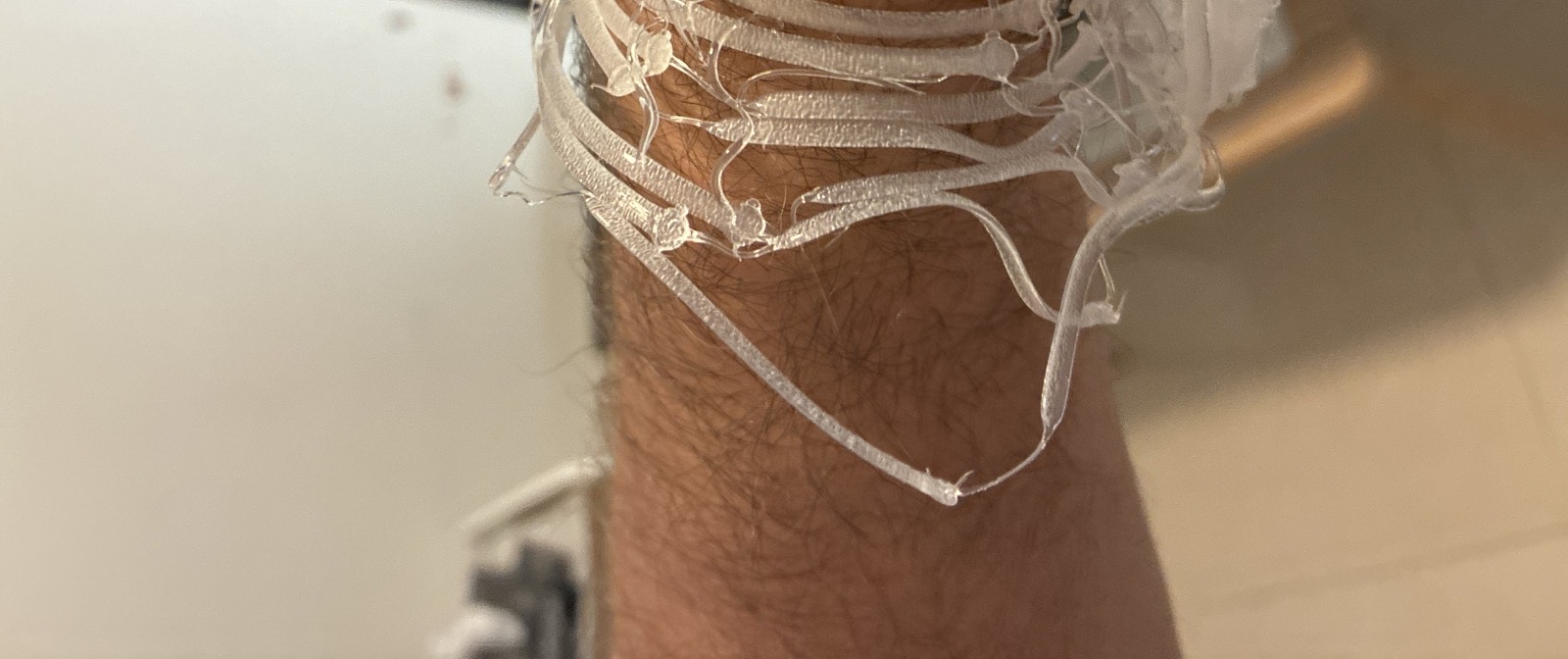
Thrown flat, wrapped warm, set in place. It fits one arm.
The strand that flies is the strand that wraps. Thrown at speed it lands as a
0.35 mm² strand. That is a cross-section, not a thickness; this page
previously called it “a third of a millimetre thick”, which reads the area as a
depth. Light enough that its own arc carries it through the air, and thin enough
that it cools to a shape in seconds while still bending willingly. A heavier bead would be
both too hot to touch and too stiff to conform.
So there is no cast, no former, no tooling of any kind. The wearer is the
mould. A piece is shaped by the hands of the person who will wear it while it is
still warm, and it fits nobody else. How long that window lasts has not been measured.
The working note this page draws on lists it as the single most useful unmeasured number
here, so measure your own with an IR thermometer rather than trusting a figure. That is not a
limitation being made into a virtue. It is the reason the object cannot be mass-produced.
The fitting is the manufacturing.
It arrived by accident, which is the third time that has happened here. A curl that lifted off
the plate became the forming idea. A petal sized wrong three separate ways became a field of
glass loops. Those loops, wrapped around a forearm before they cooled, became this. Nothing in
that sequence was designed. The process has a vocabulary of its own, and it keeps speaking
before anyone has learned to control it.
Up for grabs, and nobody is on any of these
These are not a roadmap and not a promise. They are the directions the engine already reaches
and nobody has taken. Each names the generator that would make it and the one thing still
unmeasured, so you can start tonight without asking anyone.
For wearables the fitting problem is solved by the material: print flat,
form warm against the body. Generator solid.py.
Unmeasured: the safety window, meaning how many seconds pass between 45 °C and too
stiff to shape. Nobody has timed it.
A woven wall lit from inside is the obvious thing to do with a structure that is mostly
void, so vessels and shades. Generator nucleon.py.
Unmeasured: whether a fused junction survives being lit and warmed for hours.
A sensory line on junctions designed to snap rather than
bend. Generator nucleon.py with --weld below 1.
Unmeasured: which weld fraction snaps cleanly instead of tearing.
Surfaces that organise water into a regular droplet array. Generator
waves.py. Unmeasured: everything. This one is an idea, not a result.
The process is public, and that is the point of the page:
github.com/olegmlkvorg/crackle.
Take it. No permission, no attribution required, nothing owed back.
Archived: the bending-wall bucket attempts
Archived 2026-08-02. We have not produced a working bucket from bending walls. Three
approaches, two of them printed and one wrapped by nobody, live below exactly as they were
written, measurements and all. Wrong turns stay on the page here; that is the rule. If one
of these tempts you, the generators are in the repo and the failure notes tell you where it
bit us.
The three attempts, kept in full
One night of walls: two failures, then a colonnade
Stage, plainly: the failures below are REAL (printed, cancelled at the machine); the
colonnade printed well at 40 mm on 2026-07-28 and its full-height bucket is NOT yet
printed. Every diagram is drawn from the emitted gcode, not from intention.
The question was how to grow a bucket wall fast without wasting material. The first answer was
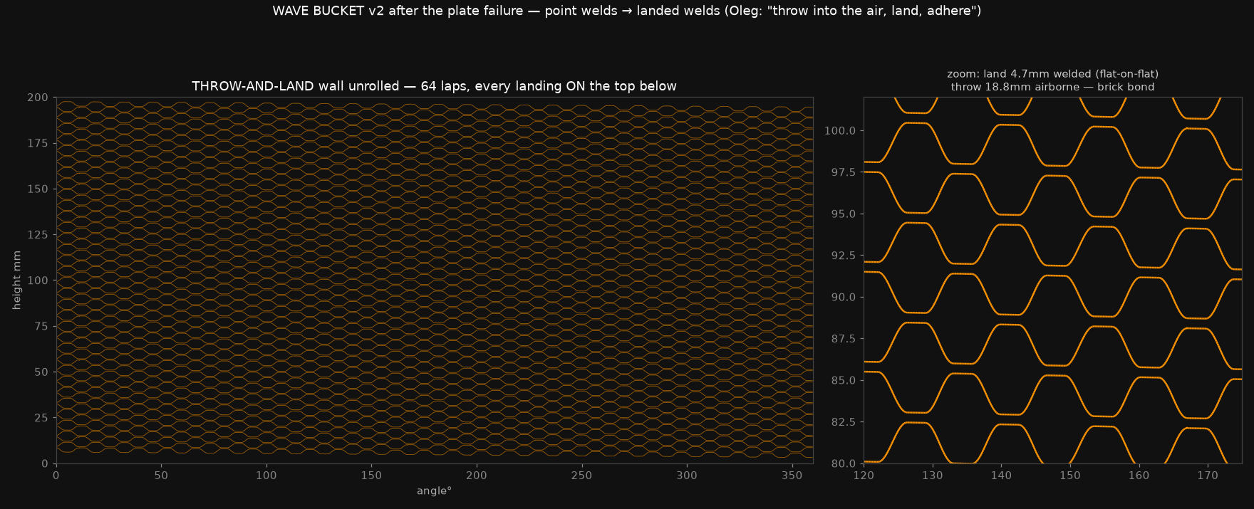
a single strand whose Z rides a sinusoid, climbing 3 mm per lap instead of 0.6. It failed
on the plate twice: crest-kiss welds are points (zero contact length, no
adhesion), and the flat-topped “throw and land” rework detached too, because its first lap
lifts progressively off the base. The accounting killed the whole family: bonds needed a
10 mm/s crawl, which is 12% flow utilisation, slower than just printing a plain wall.
What worked came from the failure’s post-mortem: don’t wave one strand. Split the
wall into towers and let the transit between them be the bridge. Small vase-mode
pillars rise in rotation (the rotation IS the cooling schedule), and the head never stops
extruding: every move to the next tower is a strand thrown through the air that lands on the
rim below and gets buried under the next laps, a mechanical lock rather than a hopeful weld. The
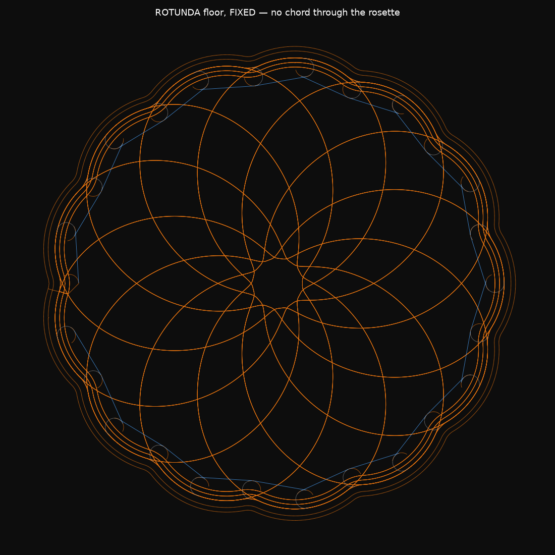
wall becomes an arcade: a rosette floor, towers at the turns of its lobed boundary, and a
woven web of flights between them.
The economics are measured from the emitted files, and they bit both ways. The first
colonnade put a tower at every turn of the boundary: 26 towers of Ø8 sum to 104%
of the plain wall’s perimeter, so with a three-strand web it cost 1.75× a
plain single-line wall. Halve the towers, keep one wave strand per bridge level, and the
same structure lands at 0.75×, a wall with daylight through it, cheaper
and faster than a solid one. The knob that looks aesthetic (tower density) is the economics.
Three defects never reached the plate because the validator reads the emitted file: a
197 mm chord extruded straight through the rosette (a gap-close between strokes that
start on opposite sides), 539 nozzle-dives from laying the wave before the strand it crosses,
and a 0.373 mm systematic collision that turned out to be two strands parametrised over
different lengths. Each was found by measurement, and the fix for the last one is the nicest
line of the night: give the wave the same height field as the chords it crosses, and
every crossing becomes a mid-air weld by construction.
Unproven until the full bucket prints: whether the arcade holds its shape at
200 mm, whether ~40 mm flights stay crisp that high, and what the rim wants at the
top. Generators: towers.py, rotunda.py in the public repo below.
The morning after: the wall refuses to be printed vertical
Stage, plainly: this design is generated and machine-validated but NOT printed, and the
wrap it depends on has NOT been performed. The diagram is drawn from the emitted gcode.
The colonnade above worked, but its economics only beat a plain wall after thinning it
twice, and the person who has to trust the bucket looked at the full-height render and
said no. Their counter-proposal inverts the whole problem: stop fighting gravity.
Print the floor with a short wall stub. Print the wall FLAT on the plate, two layers at full
speed with nothing in the air. Then warm it on the 120 °C bed and wrap it around
the stub by hand. Wrapping flat to cylinder is single curvature, the one
transformation a flat sheet performs without complaint, and the two hand-forming
successes on this page (the cuff, the flower) were exactly that move.
One panel of three: solid rails that become the bucket’s hoops, an interior of
interleaved petal lenses, the floor’s rose curve unrolled, with a smaller petal
nested in each. Nothing runs straight up (nothing to kink on the bend); the half-petals at
each edge complete each other across the wrapped seam; each panel ends in a 6 mm tab
that overlap-welds onto the previous one. The whole bucket (floor, stub, three panels)
is ~131 g and ~29 minutes of machine time, 42% of a solid wall,
with the third dimension supplied by two warm hands instead of sixty airborne minutes.
Unproven: the forming window (how long a warm sheet stays wrappable, still the
most useful unmeasured number in this whole vertical) and the strength of a hand-pressed
seam weld. The first wrap is the experiment.
Round two: the client said “ugly”, so the wall became a frieze
Stage: this panel WAS PRINTING when this first deployed, on 2026-07-28. Whether it
finished is not recorded here, and the wrap that turns two flat sheets into a bucket wall
has not happened. Diagram from the emitted gcode.Corrected 2026-08-11: this read “is PRINTING as this deploys”. A present
tense pinned to “this deploys” does not merely go stale, it re-asserts itself
every time the page ships. It shipped again on 2026-08-09 and no panel was printing.
The first flat panel printed and failed review in one sentence: structurally weak (an
open net of strands meets only at points, and points don’t weld, the same physics that
killed the wave wall) and ugly. The redesign changed construction class instead of
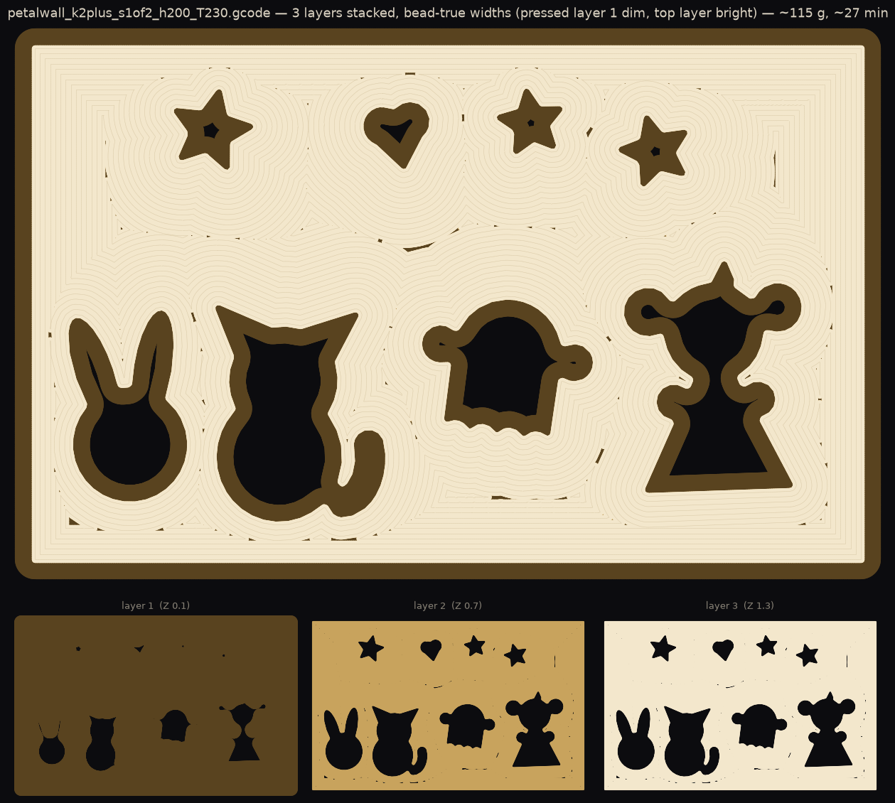
parameters: a connected sheet whose concentric fill ripples around
character-shaped windows. Light does the drawing. Every window edge is a
closed multi-bead ring welded along its whole length; three layers instead of two; two
panels instead of three, sized so the already-printed floor survives unchanged.
The honest ledger: strength cost the material win. The full bucket now weighs about the
same as a plain solid wall. What the fold-flat route still buys is the part that cannot
be printed vertically at all: a patterned, backlit-friendly wall formed by hand in
seconds, on a machine that only ever printed flat sheets at full speed.